Servo and Joystick
Welcome back for workshop 3! This time we will learn how to connect the Arduino to more complex outputs using libraries.
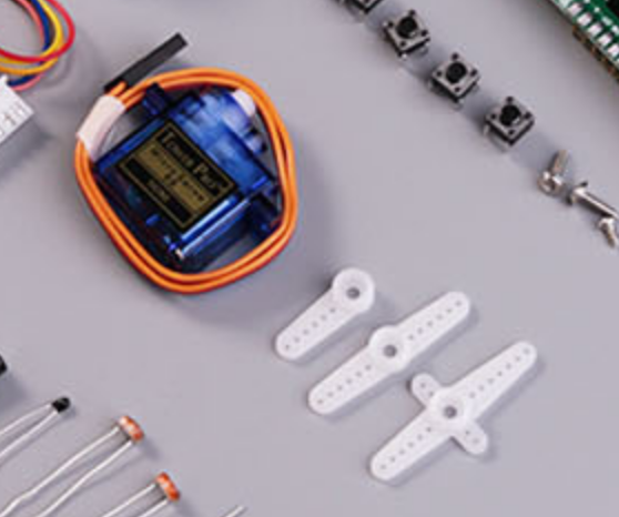
A servo is a motor module that can turn to a specific angle. It’s useful for things like robotic arms that require precise control.
Assembly and wiring
To wire up the servo you’ll need three more wires. The servo also has a “hat” that attaches on top and moves. Choose any one of the hats and snap it onto the servo.
WARNING: If you wire this backwards you’ll break the servo :( be careful!!
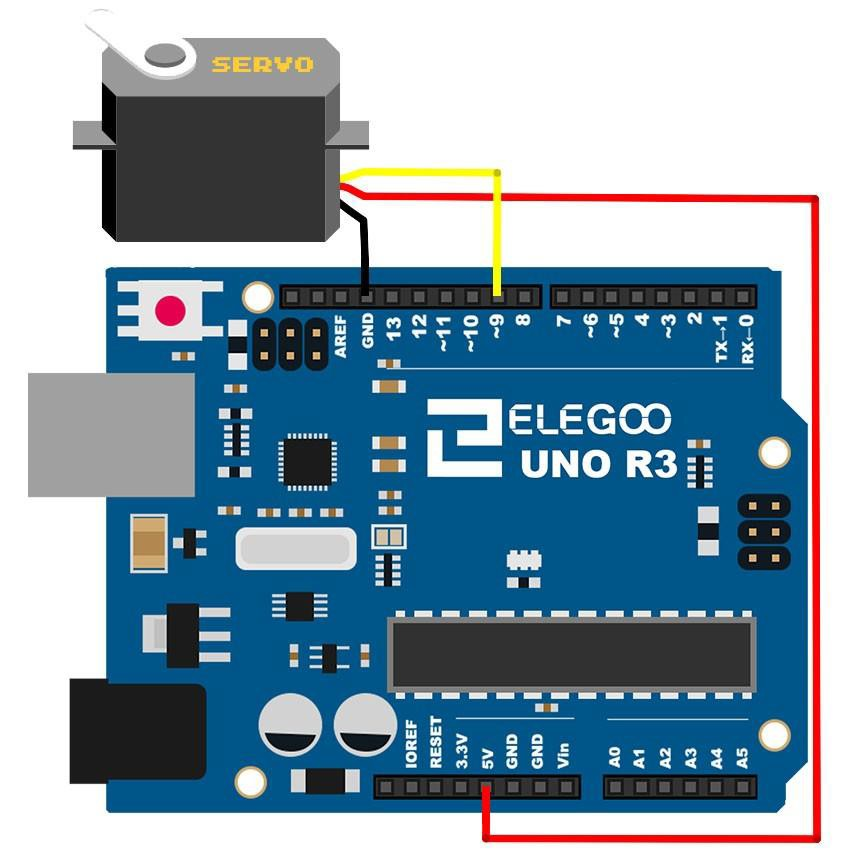
- Connect the BROWN wire on the servo the breadboard
GNDrail (blue). - Connect the RED wire on the servo the the breadboard
5Vrail (red). - Connect the ORANGE wire on the servo to pin 6 (or any PWM pin with a
~).
Controlling the servo
Once again save your old Arduino code and create a new sketch.
Servos require a complicated input signal, but thankfully someone else has written code to control them for us. This is what we call a library.
In the Arduino IDE go to Sketch > Include Library > Servo. This will add
the line #include <Servo.h> to the top of your sketch.
#include <Servo.h>

void setup() {
  // put your setup code here, to run once:

}

void loop() {
  // put your main code here, to run repeatedly:

}
Next, we’ll define a Servo object and initialize it. We define it outside
of the setup or loop functions so that it’s a global variable
accessible by both functions.
#include <Servo.h>

Servo myservo;

void setup() {
  // put your setup code here, to run once:
  myservo.attach(6);
}

void loop() {
  // put your main code here, to run repeatedly:

}
The myservo.attach function tells myservo to use pin 6 to control the
servo. Next, we’ll use a for loop to make the servo sweep back and forth.
#include <Servo.h>

Servo myservo;
int pos = 0;

void setup() {
  // put your setup code here, to run once:
  myservo.attach(6);
}

void loop() {
  // put your main code here, to run repeatedly:
  for (pos = 0; pos <= 180; pos++) {
    myservo.write(pos);
    delay(15);
  }
}
A for loop has an initial condition, stop condition, and iteration. In
this case the initial condition is to set the global variable pos to 0. The
loop will continue while pos <= 180. Each time the loop executes (iterates)
it will increment pos by one.
Within the loop we call myservo.write, which sets the angle of the servo
shaft. You can see more Servo library functions in the Servo library’s
documentation. Again, the short delay is to keep the servo
from having to move too quickly.
This first loop moves pos from 0 to 180 degrees, but we want to move it
back from 180 to 0 as well. We achieve this with a second for loop within
loop.
#include <Servo.h>

Servo myservo;
int pos = 0;

void setup() {
  // put your setup code here, to run once:
  myservo.attach(6);
}

void loop() {
  // put your main code here, to run repeatedly:
  for (pos = 0; pos <= 180; pos++) {
    myservo.write(pos);
    delay(15);
  }
  for (pos = 180; pos >= 0; pos--) {
      myservo.write(pos);
      delay(15);
  }
}
Upload this code to see the servo sweep back and forth! This code is also
available as an example in the Servo library under
File > Examples > Servo > Sweep.
Wiring the joystick
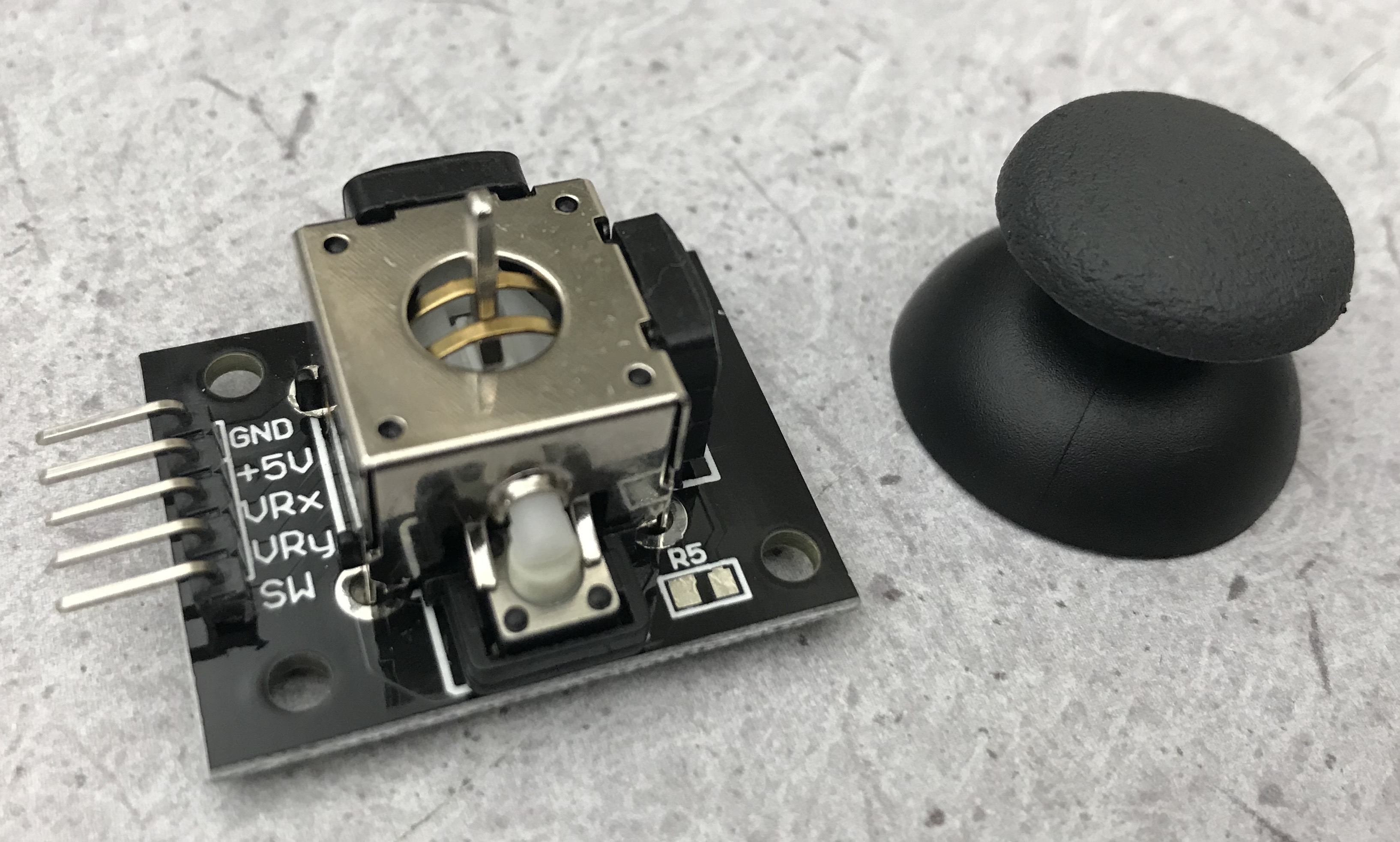
Now let’s use a joystick to control our robot arm! The joystick in the kit comes separate from its “hat”, so be sure to put them together first.
You’ll also need 3 wires with exposed wire on one side and pins on the other side (male to female wires) because the joystick has pins of its own.
The joystick pins have their own labels, so wiring them should be straightforward.
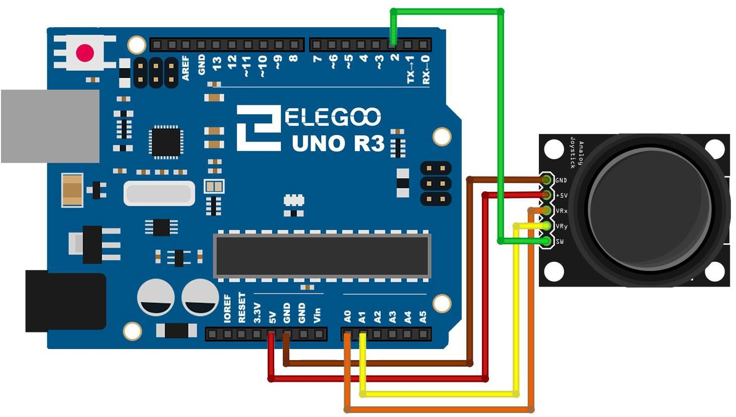
- Connect the joystick
VCCto the breadboard5Vrail (red). - Connect the joystick
GNDto the breadboardGNDrail (blue). - Connect one of the joystick data pins
VRxorVRyto pinA1on the Arduino.
VRx and VRy report movement in the X and Y directions, respectively. The
SW pin is a switch (button) click obtained by clicking down on the
joystick. Feel free to wire them all, but we will use VRy.
Coding the joystick
Open up a new file with just the Servo initialization.
#include <Servo.h>

Servo myservo;

void setup() {
  // put your setup code here, to run once:
  myservo.attach(6);
}

void loop() {
  // put your main code here, to run repeatedly:
}
Next, call analogRead in loop to read the joystick’s Y tilt.
#include <Servo.h>

Servo myservo;

void setup() {
  // put your setup code here, to run once:
  myservo.attach(6);
}

void loop() {
  // put your main code here, to run repeatedly:
  int joy = analogRead(A1);
}
Recall that the Arduino has a 10-bit ADC, so joy could be any number
between 0 and 1023 (2^10 - 1). However, myservo.write takes an angle
between 0 and 180 degrees. We’ll use the map function to map joy into the
range of 0-180.
#include <Servo.h>

Servo myservo;

void setup() {
  // put your setup code here, to run once:
  myservo.attach(6);
}

void loop() {
  // put your main code here, to run repeatedly:
  int joy = analogRead(A1);
  int angle = map(joy, 0, 1023, 0, 108);
  myservo.write(angle);
  delay(15);
}
Upload this and you’ll be able to control your motor with your joystick!
Bonus exercise: Wire up the other joystick axis and/or toggle button to control something else on your breadboard, like LED brightness or RGB LED color.
If we have enough time, we’ll wire up an even more complicated module next.
< Previous: Light Sensor · Next: LCD Screen >
This content is licensed under CC BY-NC-SA.