Light Sensor
Now we’ve done digital input, so let’s turn to analog input. We’ll use a light-dependent resistor to turn our Arduino into a light sensor.
Gather materials
Pull out a light-dependent resistor (LDR) from your kit. It looks kind of like a regular resistor, but it has a wiggly line on top.
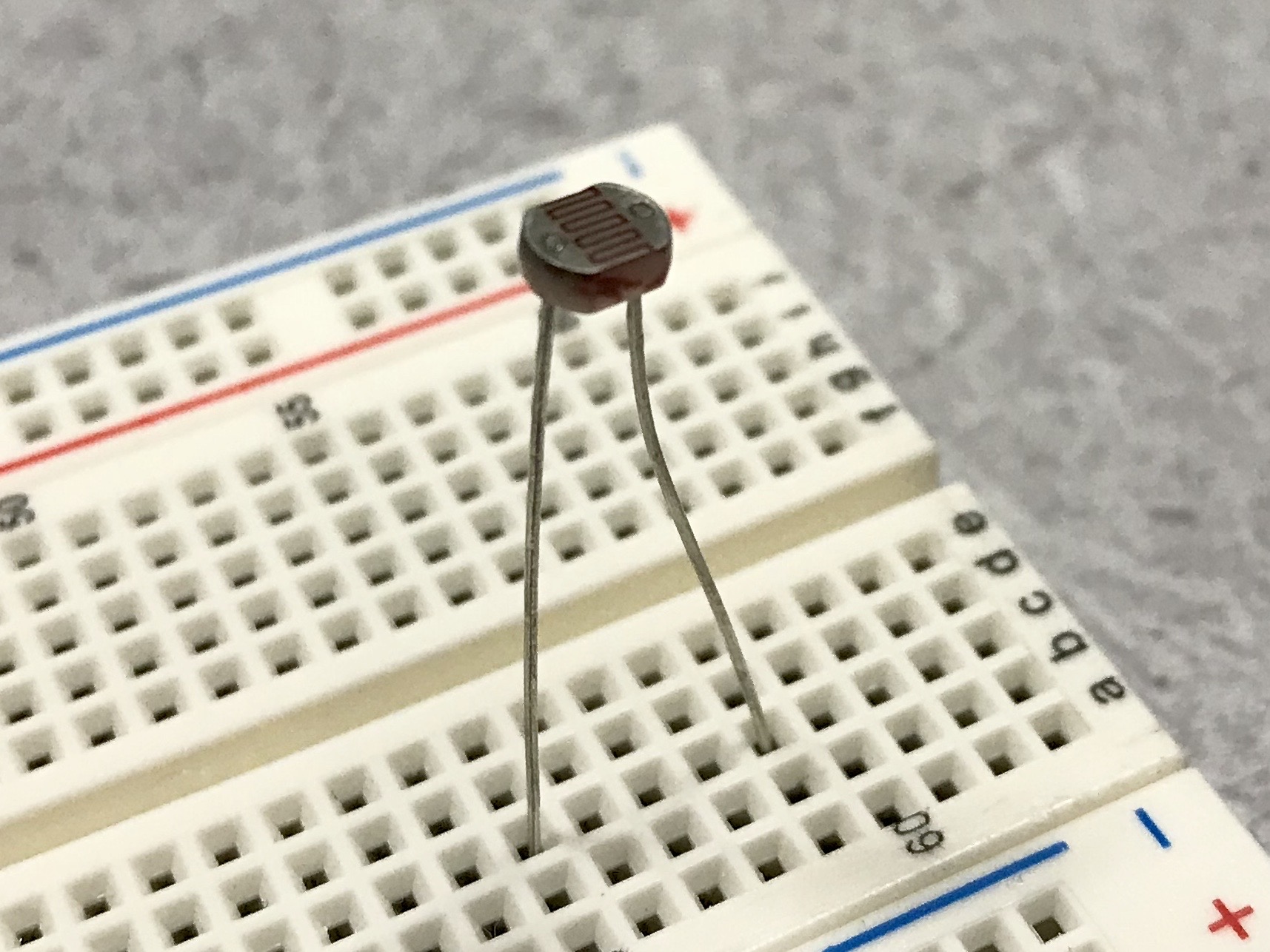
As its name suggests, a light-dependent resistor is a resistor whose resistance varies with light. We can make a clever circuit to measure this change in resistance as a change in voltage, also known as an analog signal.
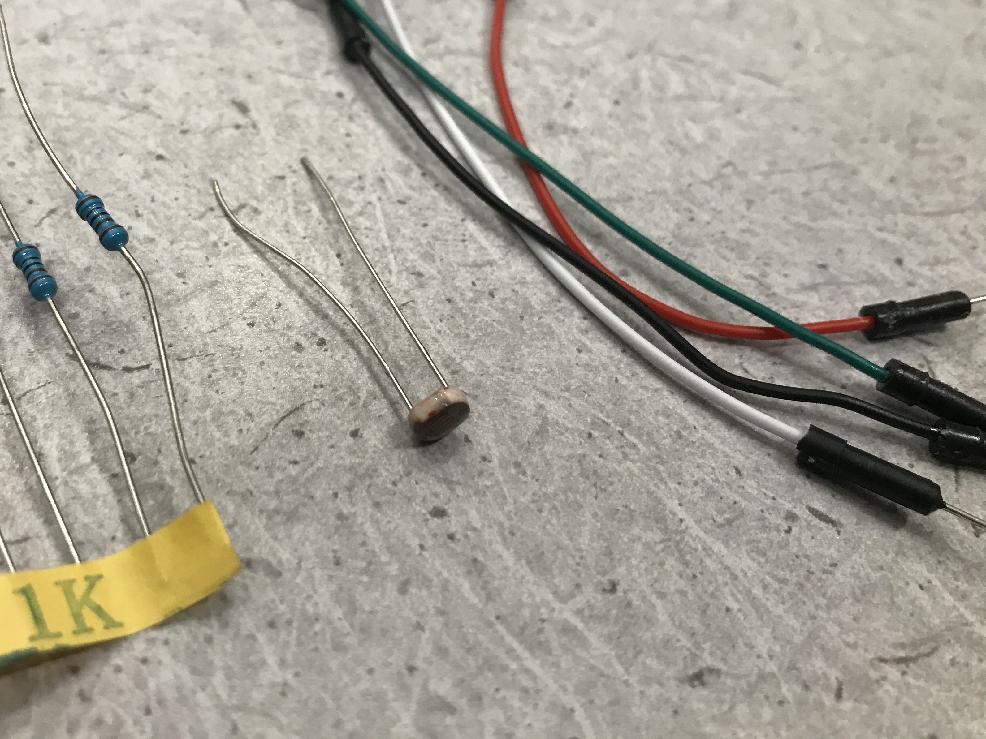
To wire the circuit you’ll also need a 1 kOhm (kilo-Ohm) resistor and four more wires. A 1 kOhm resistor has a brown-black-black-brown-brown stripe pattern. The paper holding the resistor might also say “1K” on it.
Wiring a voltage divider
The circuit we’re wiring is called a voltage divider. You can learn more about the math of how it works here.
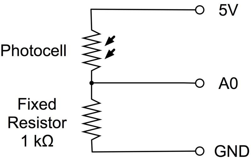
The light-dependent resistor (“photocell”) is connected to 5 volts (5V) of
power on one side of the divider and the 1 kOhm resistor is connected to
ground (GND) on the other side. We read the voltage from the middle into one
of the Arduino’s analog-to-digital converter (ADC) pins, A0.
First, add a wire from the 5V pin to the red rail that runs along the
breadboard. This is commonly used for power. Next, add a wire from the
breadboard power rail to a row with one leg of the LDR. Connect the
other leg of the LDR to A0 on the Arduino. Add one leg of the
fixed 1 kOhm resistor in that same row with the second leg of the
LDR. Finally, connect the last wire from the other leg of the fixed
resistor to the breadboard’s GND rail (the blue rail).
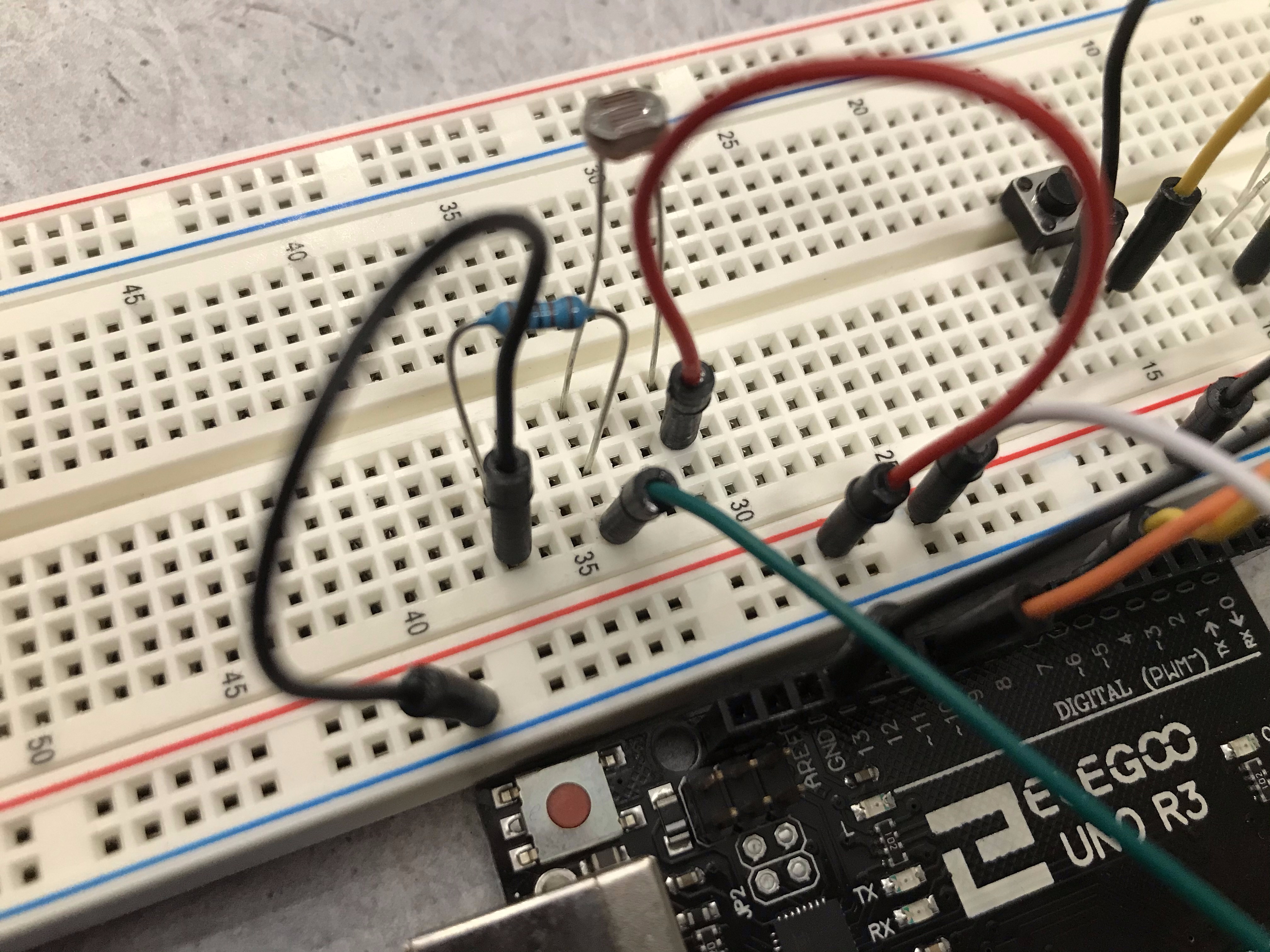
This is one way to wire up the voltage divider, but it’s better to use the diagram instead of copying from a photo.
The Serial Monitor
Now let’s make a light sensor! As usual, save your previous sketch and create a new one.
void setup() {
  // put your setup code here, to run once:

}

void loop() {
  // put your main code here, to run repeatedly:

}
We’re going to start by initializing Serial, which lets us send and receive messages from the Arduino over USB.
void setup() {
  // put your setup code here, to run once:
  Serial.begin(115200);
}

void loop() {
  // put your main code here, to run repeatedly:

}
The number 115200 is the baud rate, or communication rate, of the serial
communication. Now in the loop let’s read from A0 and print it to Serial.
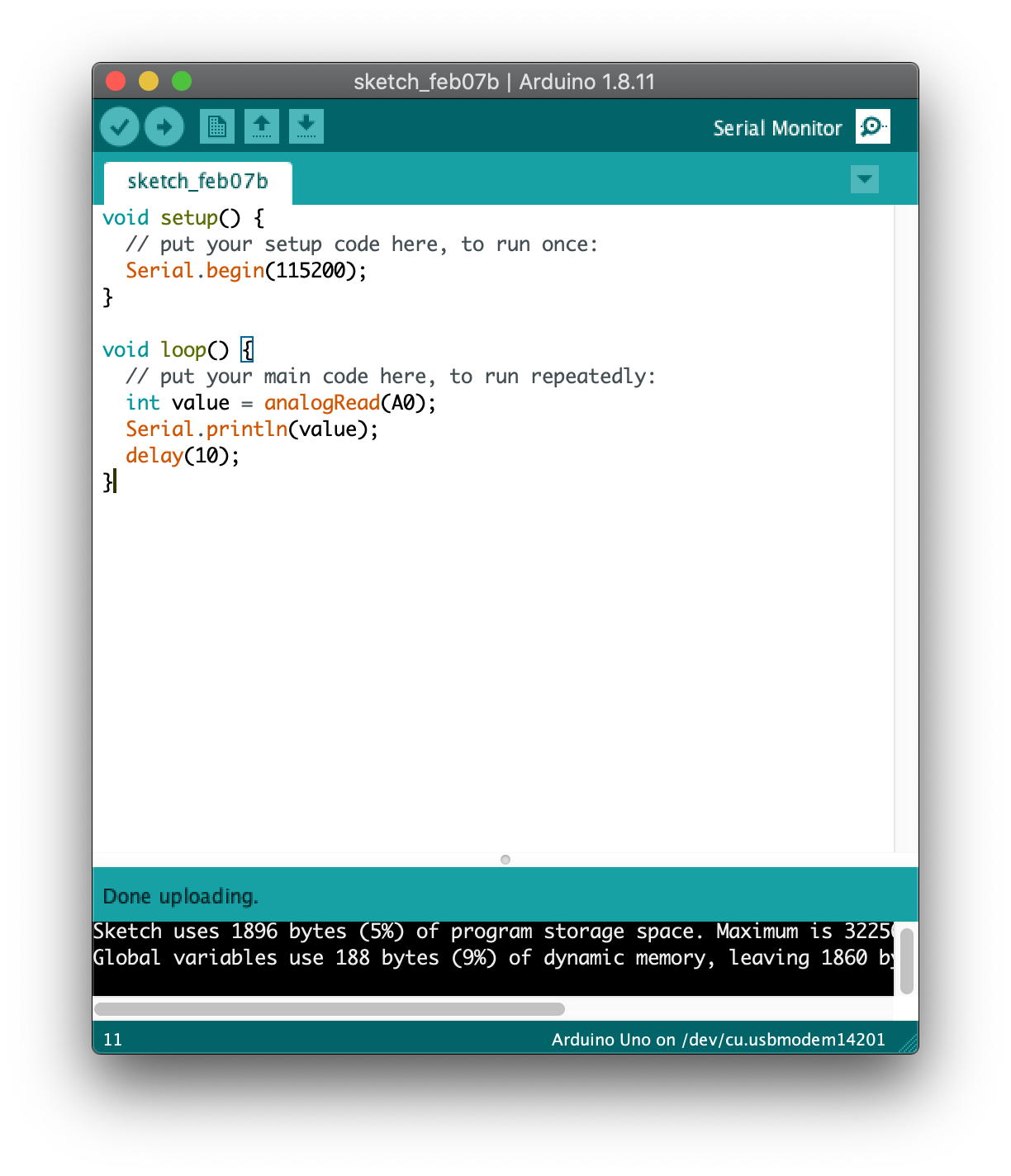
void setup() {
  // put your setup code here, to run once:
  Serial.begin(115200);
}

void loop() {
  // put your main code here, to run repeatedly:
  int value = analogRead(A0);
  Serial.println(value);
  delay(10);
}
As you would expect, analogRead reads from a value from A0. The
brightness signal is analog, so the analog-to-digital converter (ADC)
associated with A0 converts it from an analog voltage to a number between 0
and 1023 (2^10 - 1, because this board has a 10-bit ADC). This
tutorial explains ADC in further detail.
Serial.println prints value to the Serial Monitor. We also included a
small delay of 10 milliseconds to slow down the loop.
Now it’s time to upload the code! Nothing in this code connects to any output like an LED, so you won’t see anything happen once it’s uploaded. You will only see output in the Serial Monitor. Once the Arduino IDE says “Done Uploading”, click the mangifying glass icon in the top right corner of the window to open the Serial Monitor.
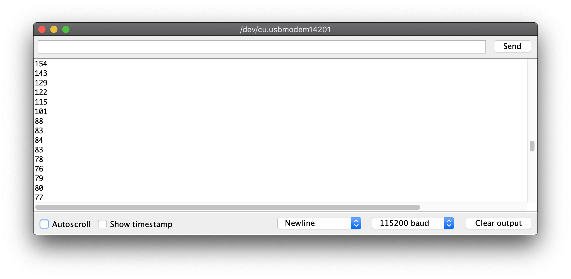
Once you open the Serial Monitor, you should see values streaming down the screen. Wave your hand over the LDR to see the numbers change!
This is exciting, but it can get even more exciting. Close the Serial Monitor and instead open the Serial Plotter under Tools > Serial Plotter.
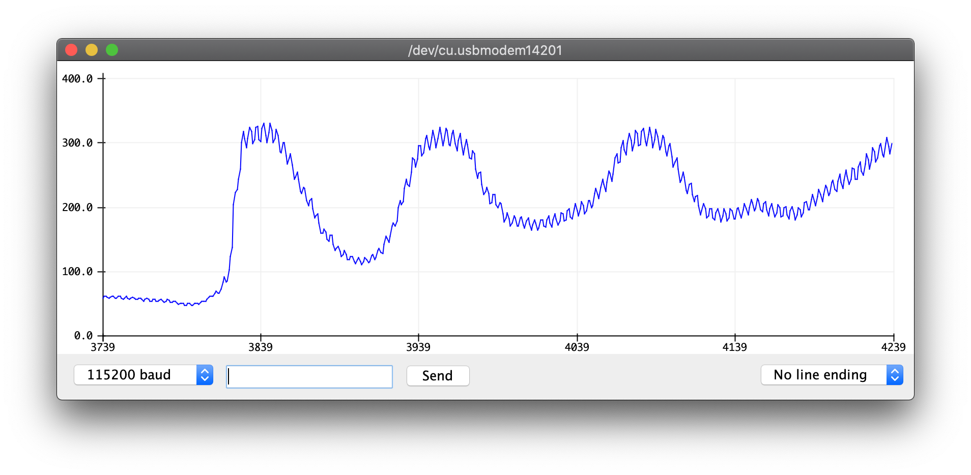
Congratulations, you’ve now made a light sensor with a cool graphical display!
Bonus exercise 1: Make a nightlight – turn on the LED if the room is dim and off otherwise.
Bonus exercise 2: Replace the LDR with the thermistor (temperature-dependent resistor) or the humidity sensor and do something cool with it.
Wrap up
That’s the end of workshop 2! Again, leave your hardware at your table and remember where you sat.
< Previous: Button · Next: Servo and Joystick >
This content is licensed under CC BY-NC-SA.