Button
Welcome back! As a quick recap, in the last lesson we learned about the Arduino board itself, digital output (blinking an LED), analog output (dimming an LED), and we ended with the challenge of wiring up an RGB LED. Each of these LED tasks was an exercise in output. Now, we’ll learn about input.
Wiring
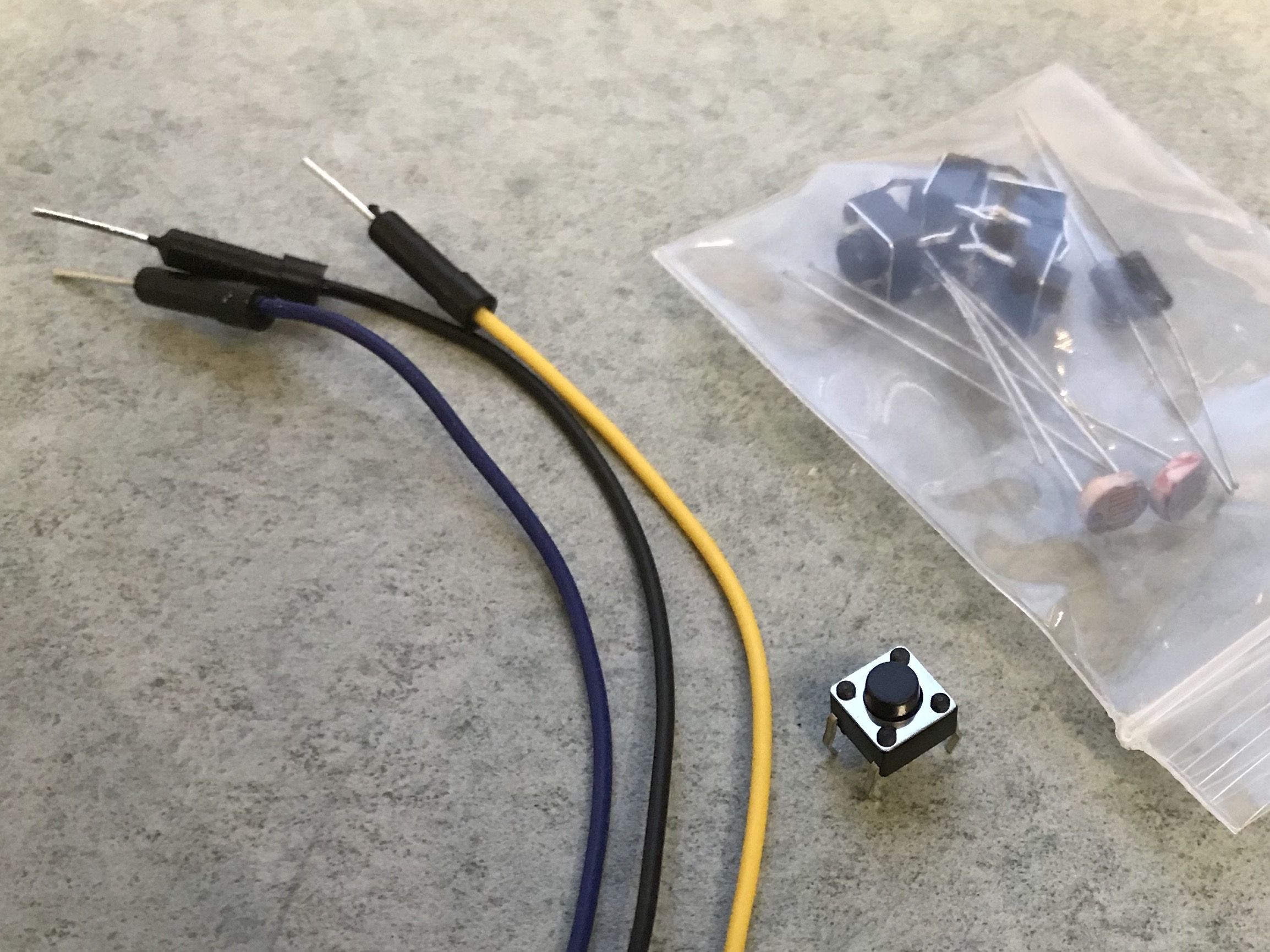
The simplest input is a button. Let’s start by wiring it up! Take out the button and three wires from your kit.
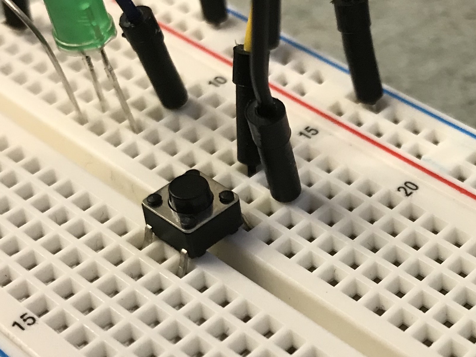
To put the button into the breadboard it needs to straddle the gap between the two sides of the breadboard. Make sure that it’s fully pressed in to the board.
Next, remove the wire from the LED to GND. Instead, wire it from GND to the blue rail that runs along the breadboard. This will make it easier to provide ground to all the things you wire up. Refer to the breadboard photo from the Blink exercise for reference.
Now you can re-add a new wire from the blue GND row to the LED short leg, then add another wire from the blue GND row to one pin of the button. Finally, add one wire from the other side of the button to pin 7. What does “the other side” mean? Internally, the button is a switch that closes and makes a connection between the two sides when the button is pressed.

In this diagram, this means that A and D are connected and B and C are connected. See this lesson by Adafruit for more details on digital input.
Coding the button with digitalInput
Now that the button is wired we’re ready to program! Open up your Arduino
IDE, save your old sketch, and make a new sketch. We’ll be using the button
to control the LED, so set up the LED in setup again.
void setup() {
  // put your setup code here, to run once:
  pinMode(11, OUTPUT);
}

void loop() {
  // put your main code here, to run repeatedly:

}
Next we need to set the pin mode of the button pin to INPUT_PULLUP.
void setup() {
  // put your setup code here, to run once:
  pinMode(11, OUTPUT);
  pinMode(7, INPUT_PULLUP);
}

void loop() {
  // put your main code here, to run repeatedly:

}
The INPUT part makes sense – this pin is for input and not output. But
what does PULLUP mean?
As shown in the diagram above, when the button is not pressed the circuit is
open, not closed. This means that normally when you digitalRead from pin 7
the value you receive will be undefined and vary based on static electricity.
PULLUP means that instead of undefined, Arduino automatically forces the
value to be HIGH when the button is not pressed, and LOW when the button
is pressed. The value is “pulled up” when not pressed.
Now that the pin is set up we can read from it in loop.
void setup() {
  // put your setup code here, to run once:
  pinMode(11, OUTPUT);
  pinMode(7, INPUT_PULLUP);
}

void loop() {
  // put your main code here, to run repeatedly:
  int value = digitalRead(7);

}
Here we’re declaring the variable value as the result of the function
digitalRead. digitalRead is just like digitalWrite, but it reads from
the pin instead of writing to it.
Let’s turn on the LED when the button is pressed.
void setup() {
  // put your setup code here, to run once:
  pinMode(11, OUTPUT);
  pinMode(7, INPUT_PULLUP);
}

void loop() {
  // put your main code here, to run repeatedly:
  int value = digitalRead(7);
  if (value == LOW ) {
    digitalWrite(11, HIGH);
  }
  else {
    digitalWrite(11, LOW);
  }
}
Here we are using an if statement. If the condition is true (value ==
HIGH), then the code in the curly braces will execute. If the condition is
false, the code in the curly braces after else will execute.
Remember that the button result may be unintuitive because of PULLUP –
value == LOW means that the button is pressed!
Go ahead and upload this code and try it out!
Bonus exercise 1: Make the button into a light switch, where pressing and *releasing the button toggles the LED on and off.
Bonus exercise 2: Click to control the color of your RGB LED if you’ve *wired it up.
< Previous: RGB LED · Next: Light Sensor >
This content is licensed under CC BY-NC-SA.