Blinking LEDs
Let’s put down the Arduino board for the moment and turn our attention to the Arduino IDE. The Arduino IDE (integrated development environment) is where we write code and upload it to the board. Just like you may write papers in Microsoft Word, you can write Arduino programs in the Arduino IDE.
Since you’re working in partners, each of you can write code individually and take turns uploading it to the board.
Let’s write a basic program to blink the on-board LED on and off.
Blank sketch
You’ll notice that the Arduino IDE starts up with a blank file like this.
void setup() {
  // put your setup code here, to run once:

}

void loop() {
  // put your main code here, to run repeatedly:

}
As it says in the comment, the setup function is run once as soon as the
program starts up. Then, the loop function runs over and over.
Setting up the pin
Let’s add one line in to setup.
void setup() {
  // put your setup code here, to run once:
  pinMode(13, OUTPUT);
}

void loop() {
  // put your main code here, to run repeatedly:

}
As you may recall from our board overview, “pins” are the labeled black holes on the edges of the board. They allow the board to reference external devices. In this case, pin 13 also refers to the board’s internal LED.
The pinMode function sets the mode of the specified pin. Here, we set pin
13 to OUTPUT mode. Each pin is explicitly for input or output, and we
choose output here to control the LED.
Writing to the pin
Next, let’s add code in loop to actually send some output.
void setup() {
  // put your setup code here, to run once:
  pinMode(13, OUTPUT);
}

void loop() {
  // put your main code here, to run repeatedly:
  digitalWrite(13, HIGH);
  delay(1000);
  digitalWrite(13, LOW);
  delay(1000);
}
The digitalWrite function writes some value to a pin. A digital value can
either be HIGH or LOW (on or off, 1 or 0, etc.), so what this first line
means is we send a HIGH voltage to pin 13, turning the LED on.
Next, we call delay. delay pauses the execution of the program for some
number of milliseconds (ms). 1000ms is one second, so we’re delaying
execution for one second. This keeps the LED on for one second.
The next two lines turn the LED off, then delay another second. Then the loop will repeat again. This makes the LED blink!
Uploading code
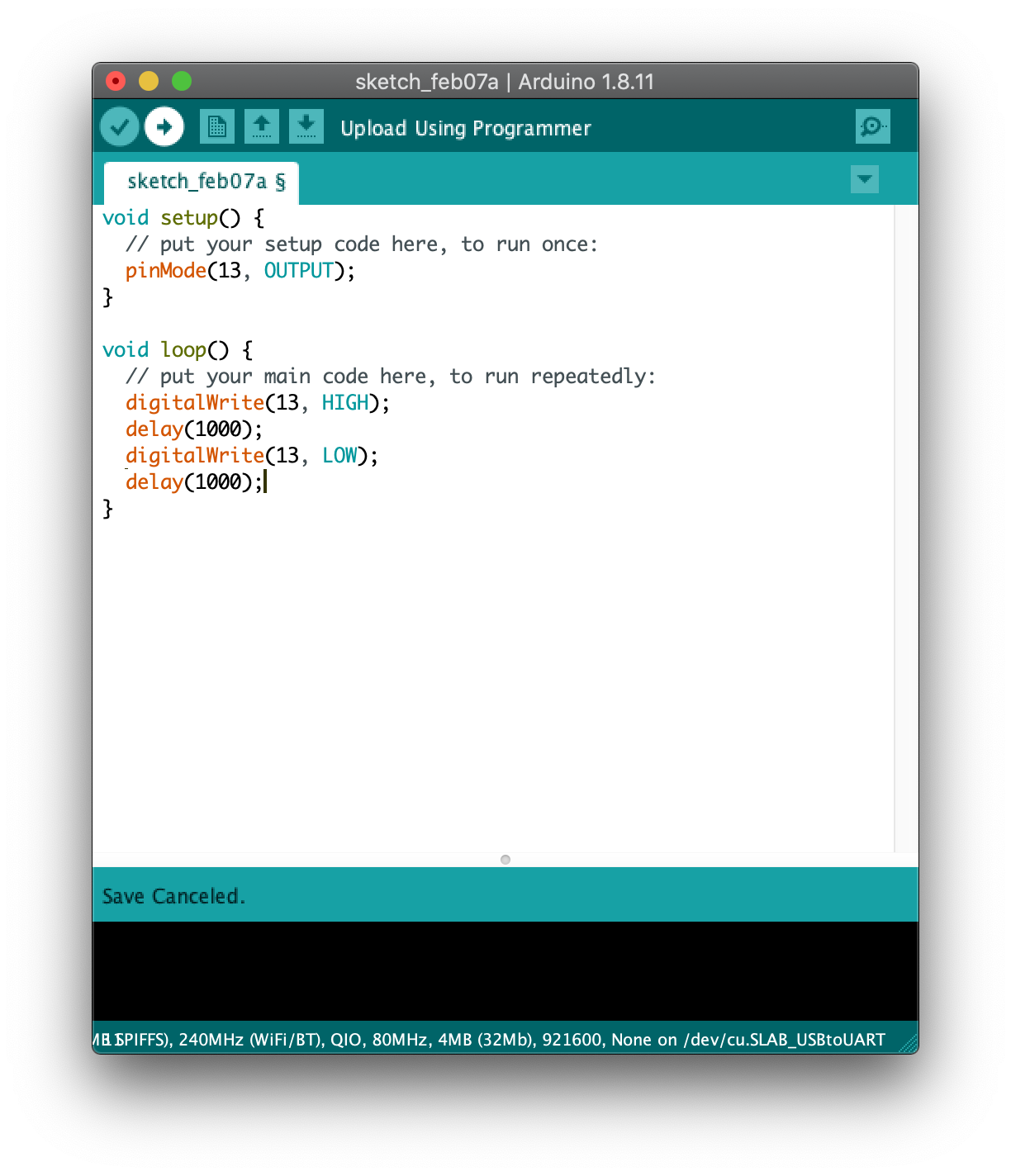
Check before you upload that you have these five lines in your sketch. If you
want to double check, you can also find this code under
File > Examples > 01.Basics > Blink in the Arduino IDE.
Now it’s time to upload! Use the USB to microUSB cable in your kit to plug
your Arduino into your laptop. Go to Tools > Port in the Arduino IDE to
confirm that the IDE has recognized the device. It might call it COM5 or
USB_to_UART or something like that. Also check that under Tools > Board
the board Arduino Uno is selected.
Finally, click the “Upload” button in the top left corner of the window to upload your code!

Hopefully your blink will look something like this! If you’ve got this working, you can play with changing the delay amount from 1000ms to something else.
Blink off-board LED
Gather materials
Now that we’ve got the onboard LED blinking, let’s try it with an LED we wire up ourselves. Open up your kit and pull out the breadboard.

If you were to rip off the back of a breadboard (DON’T DO THIS, though!), you would see how the rows and columns are connected.
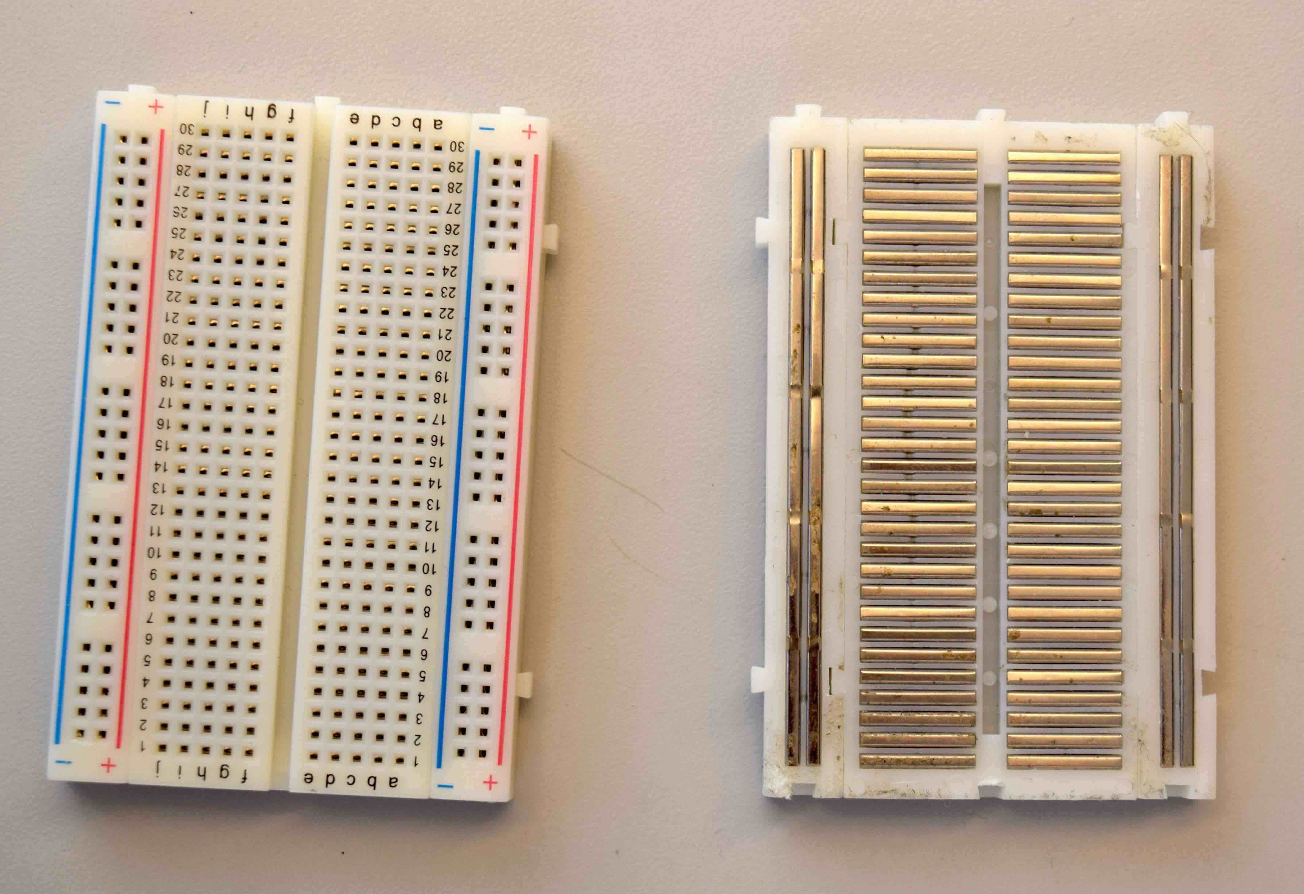
Anything connected by metal in this photo is connected within the breadboard. We’ll use this breadboard to connect the LED to the Arduino.
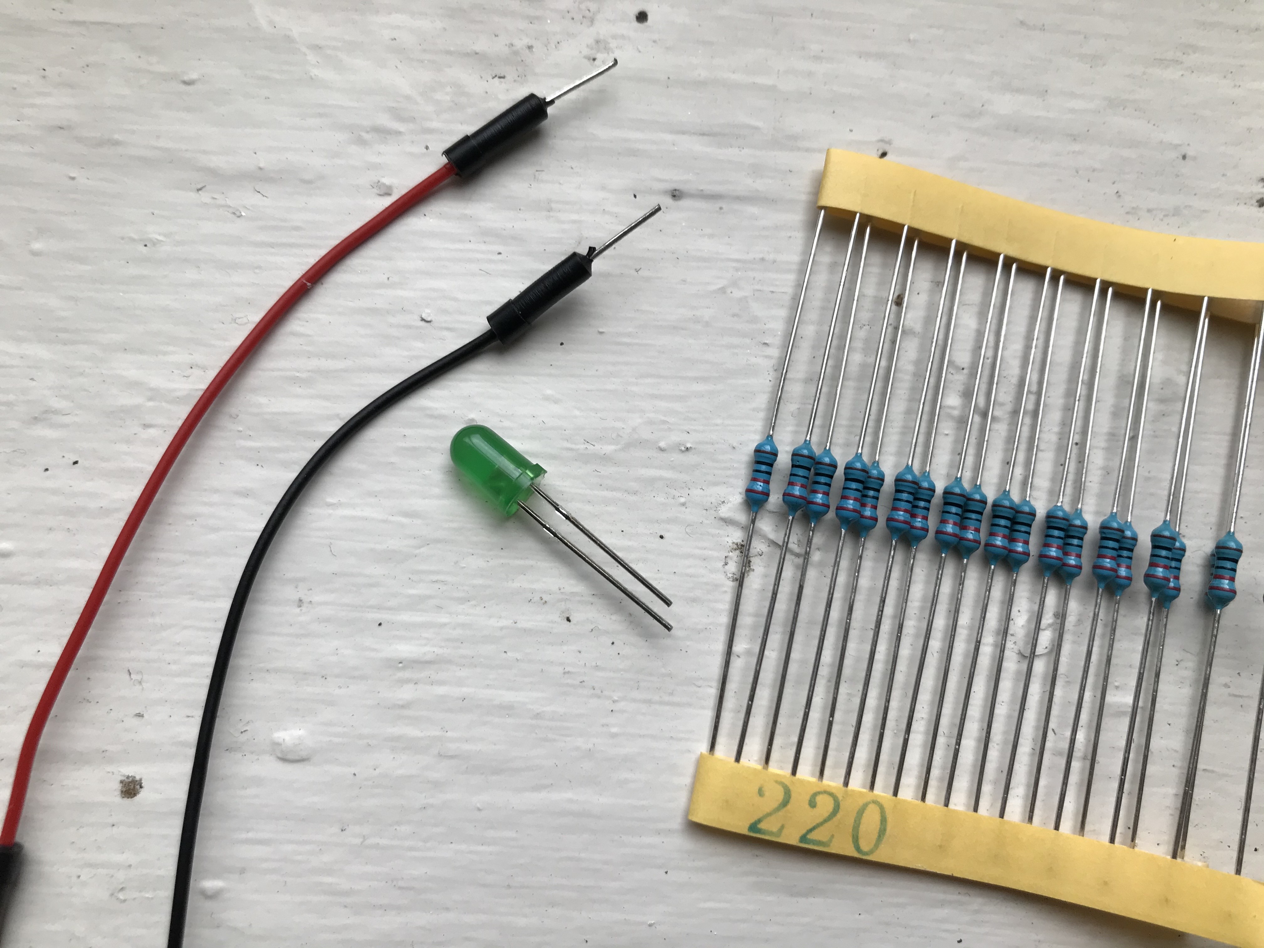
Next, take out an LED from your kit. Any color is fine!
Notice that the LED is directional: one “leg” is shorter and one is longer. Also, the plastic cover has a slightly flat edge on the side with the short leg.
Also get a 220 Ohm resistor from the kit. A 220 Ohm resistor has a red-red-black-black-brown stripe pattern. The paper holding the resistor might also say “220” on it.
Finally, take out two wires. Wires of any color are fine, but the convention is to use black for ground.
Wire up LED
Now it’s time to wire it up! Always unplug the USB power cable from your board before wiring to make sure you don’t damage anything.
Wire as follows:
- Connect a wire from GND on the Arduino to some row on the breadboard.
- Insert the LED into the breadboard so the short leg is in the same row as GND.
- Insert the resistor into the breadboard so one leg is in the same row as the long leg of the LED.
- Connect a wire from the row with the other resistor leg to the board pin 13.
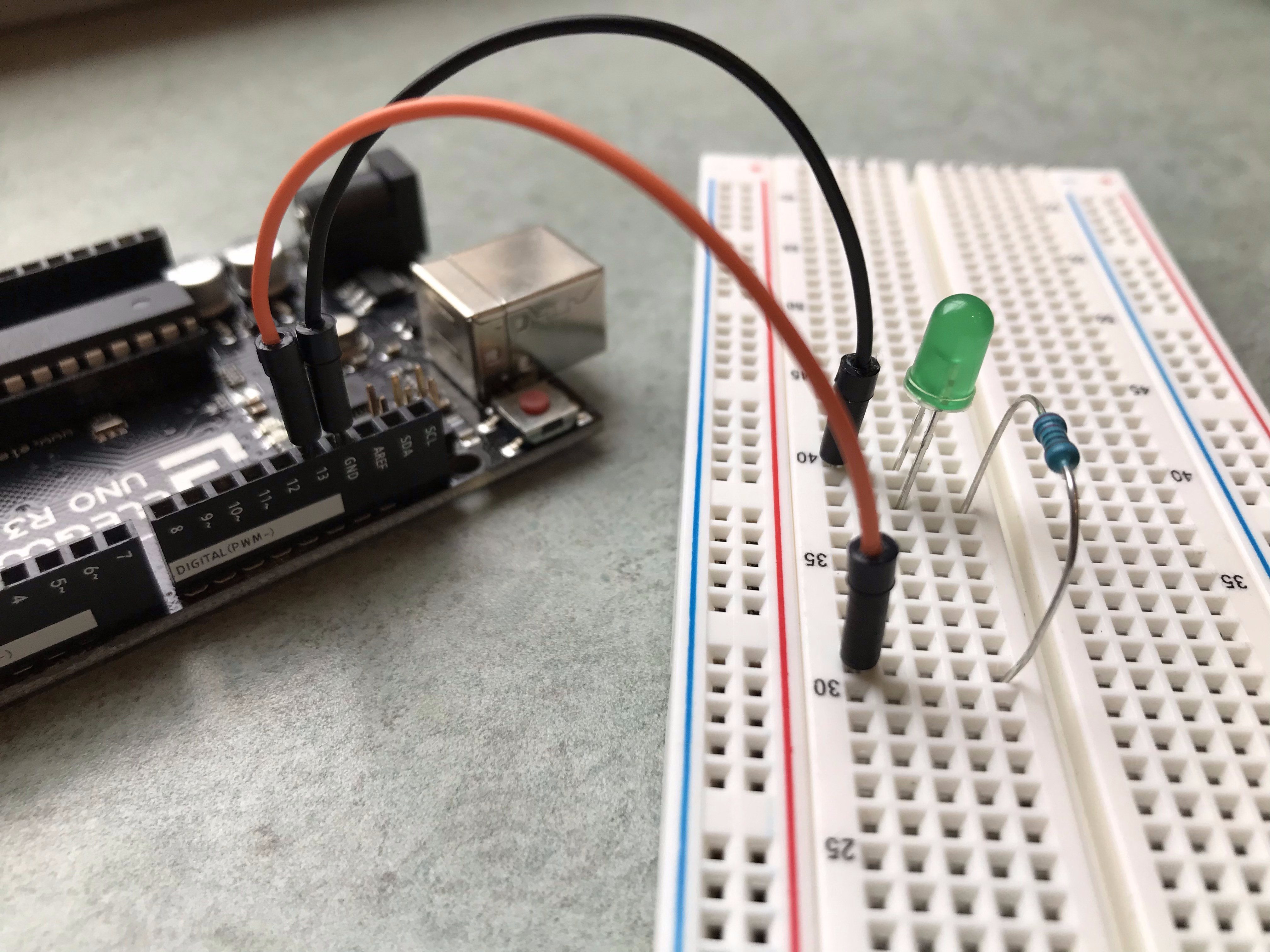
This is approximately what your wiring might look like! Now, let’s do something more advanced with this LED.
< Previous: Overview of the Board · Next: Dimming LEDs >
This content is licensed under CC BY-NC-SA.